专业胶粘剂厂家
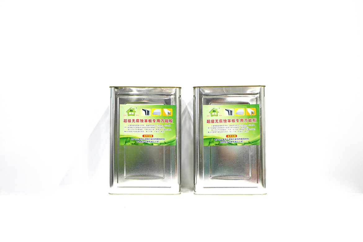
氯丁万能胶,万能胶,草坪胶,免钉胶
全国24小时咨询热线:
15588022228
本网站所有内容的解释权,
归顾家新型建材所有
氯丁万能胶,万能胶,草坪胶,免钉胶
全国24小时咨询热线:
本网站所有内容的解释权,
归顾家新型建材所有

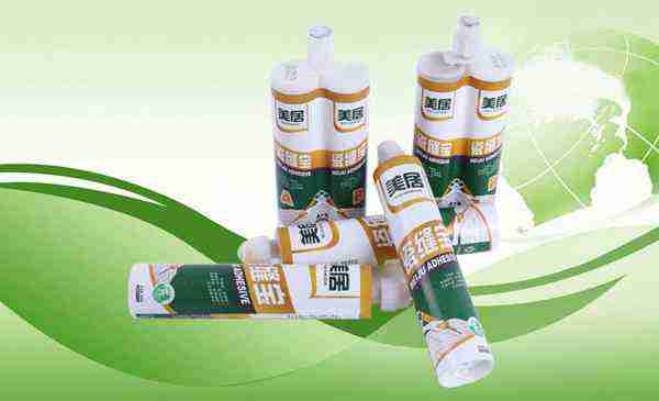
美居万能胶

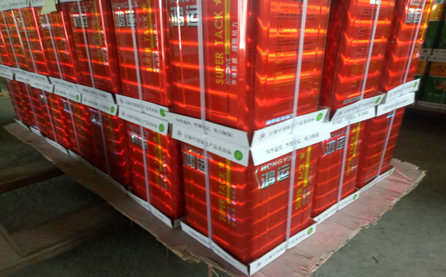
皇冠万能胶

胶霸万能胶

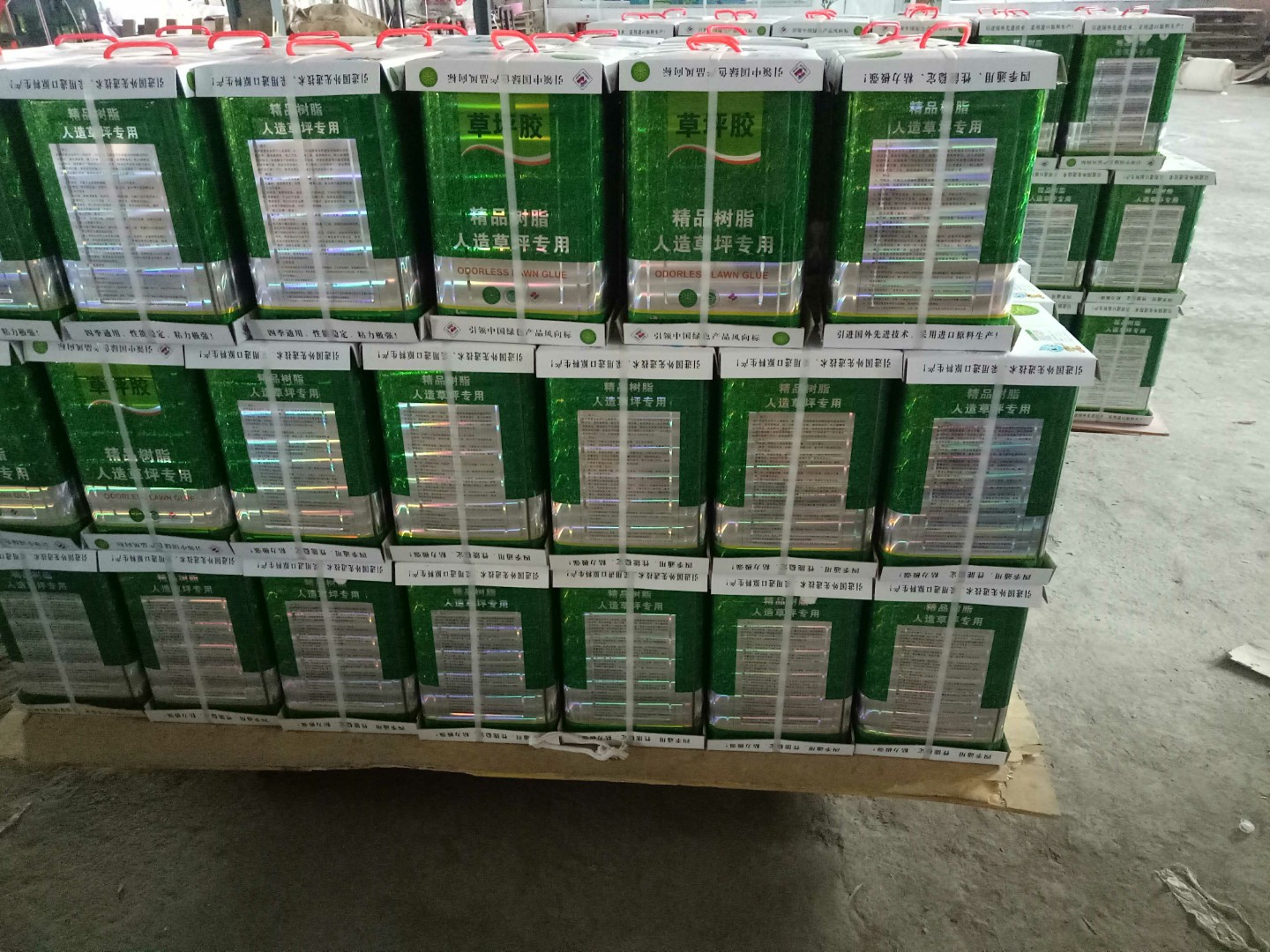
绿色家园万能胶

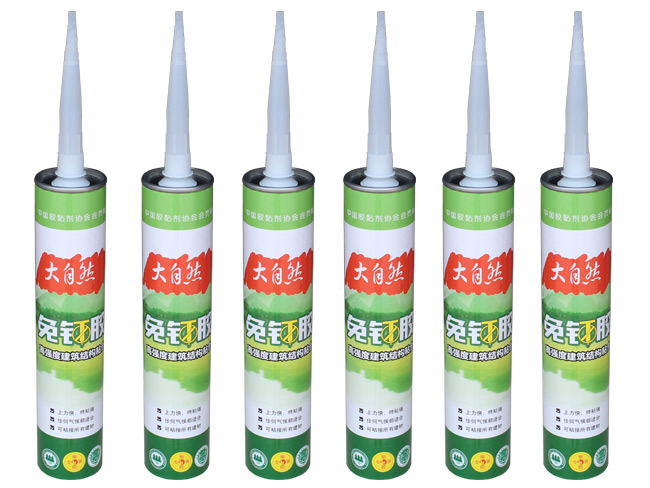
免钉胶

临沂免钉胶厂家

盾义免钉胶厂家

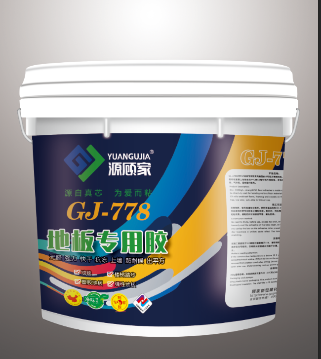
源顾家免钉胶

姚师傅免钉胶

美居免钉胶

源顾家封边胶

源顾家封边胶

美居封边胶

源顾家中性硅酮耐候胶793

瓷缝宝

美居瓷缝宝

万能胶化学名为“氰基丙烯酸酯”,最先在1942年面世,库弗的研究团队最初是想研发一种物料,用来清洁枪械瞄准器,但这种化合物却老是黏住一切对象,所以功能特多。
答:氯丁胶是由杜邦科学家 Elmer K发明的。伯勒屯 杜邦实验室由Fr.参加了一次演讲。朱利叶斯・亚瑟Nieuwland教授 化学 在Notre Dame大学。 Nieuwland的研究注重了乙炔化学,在工作期间,他生产了联乙烯乙炔,变牢固入一有弹性复合相似于橡胶,当通过时的果冻二氯化硫。在杜邦以后从大学购买了专利 权利,华莱士Carothers 杜邦接收了Nieuwland的发现的商业发展与Nieuwland合作。 杜邦集中于monovinyl乙炔领域,并且研究反应物质与氯化氢气体,制造氯丁二烯。 1937年,首例合成橡胶Neoprene(氯丁胶)被杜邦公司发明。1957年拜耳公司推出快速结晶型氯丁胶。
答:单体:无色、易挥发、有麻醉性和毒性的液体;微溶于水,可溶于很多有机溶剂;熔点为-130±2℃,沸点为59.4℃,20℃时相对密度为0.96。它具有共轭双键的一般特性,双键很活泼,容易发生加成和聚合反应。其聚合速率比丁二烯高1000倍。 氯丁胶的结构比较规整,又有极性较大的氯原子,故结晶性高,使其在室温下就有较好的粘接性能和较大的内聚强度,非常适 宜作胶粘剂,氯丁胶粘剂特性如下: 1.初始粘力大,大部分氯丁橡胶胶粘剂为室温固化接触型的, 涂胶于表面,经适当晾置,合拢接触后,便能瞬时结晶,有很大的初 始粘接力。 2.粘接强度高,强度建立的速度很快。 3.对多种材料都有较好的粘接性,所以氯丁橡胶胶粘剂也有“万能胶”之称。 4.耐久性好,具有优良的防燃性、耐光性、抗臭氧性和耐大气 老化性。 5.胶层柔韧,弹性良好,耐冲击与振动。 6.耐介质性好,有较好的耐油、耐水、耐碱、耐酸、耐溶剂性能。 7.可以配成单组分,使用方便,价格低廉。 8.耐热性较差,耐寒性不佳。 9.溶液型氯丁橡胶胶粘剂稍有毒性。 10.贮存稳定性差,容易分层、凝胶、沉淀。 11、氯丁胶实现聚合温度可控
答:氯丁胶黏剂内聚强度高、耐热、耐油、耐老化,对金属、非金属均有较好的黏合效果。用于木工、家具、制鞋、建筑、电子、轻纺、交通运输、机械等部门。可制成接触型胶黏剂。应用拼混技术改性氯丁胶乳,用丙烯酸酯胶乳与非离子氯丁胶乳拼混制成的胶黏剂,性能与溶剂型氯丁胶黏剂相当。 它的化工惰性使它非常合适为工业应用,例如垫圈,水喉和 腐蚀-抗性 涂层. 它可以使用作为基地为 胶粘剂噪声隔离在力量 变压器 设施,和作为在外在金属盒保护内容的填塞,当允许滑配合时。 氯丁胶,当以板料形式时,它的松软一贯性地它难以折叠。 氯丁胶是常用的材料,它提供优秀绝缘材料。 氯丁胶潜水衣通常是大约5毫米厚实的,和在中等价格范围与更加便宜的材料比较例如 尼龙 并且橡胶。 然而,氯丁胶比适于吸入的织品较不昂贵的。 氯丁胶拥有良好的粘结力,目前是广泛用于汽车行业,在PVC,真皮与ABS+PC骨架覆合有着较好的运用。氯丁胶经历了含苯溶剂和无苯溶剂两个阶段。由于人们越来越关注三苯对人类健康的影响,VOC指标渐渐走进人们的视野,水性氯丁胶将是未来发展的重点。 为潜水和 保温保护应用,空域在氯丁胶充满氮气为它的绝缘材料价值。 这也使材料相当轻飘飘,并且潜水者必须通过佩带重量补尝此。 厚实的潜水衣被做在他们的冷水保护的极端通常由7毫米做成厚实的氯丁胶。 值得注意的是,,因为氯丁胶包含空域,材料压缩在水压下,得到稀释剂在更加了不起的深度。 如此一件7毫米氯丁胶潜水衣提供较少曝光保护在水的一百英尺以下比在表面。 最近前进在氯丁胶为潜水衣是“超级屈曲”结合的品种斯潘德克斯弹性纤维入氯丁胶为一种更加伟大的灵活性。 最近,以氯丁胶为粘接材料的包括笔记本计算机, iPod , 遥控器等。
答:氯丁胶乳是一种高分子的聚合物,属于氯丁橡胶制品中的一种。氯丁胶乳属于水乳型产品,根据乳化剂的不同,常用产品大致可分为阴离子氯丁胶乳、阳离子氯丁胶乳。氯丁胶乳性能稳定,可抵抗酸碱腐蚀;抗渗性能优越,粘结力强,常常应用于防水防腐工程。 氯丁胶乳生产的氯丁胶乳以及衍生产品,已经广泛应用于高层建筑外墙防水、天面防水、地下室防水以及防腐水池。氯丁胶乳根据聚合度以及部分聚合成分的不同,大致颜色为米黄色以及乳白色。阳离子氯丁胶乳由于阳离子乳化剂的不稳定性,在与其他材料搭配使用时,常常导致絮凝,而导致应用效果变差,甚至破坏本来的性能。 在三苯溶剂型氯丁胶的使用历史将要结束,无三苯溶剂型装饰胶将被推出时。应开发研制绿色产品,加大投资开发力度,实现接着剂产品的更新换代,大力发展环保型合成接着剂。重点发展无三苯溶剂型氯丁胶的研究、开发、推广、使用,加快淘汰含三苯溶剂型氯丁胶。